A Canadian Company
Jaguar V-12 Ignition Repair |
|
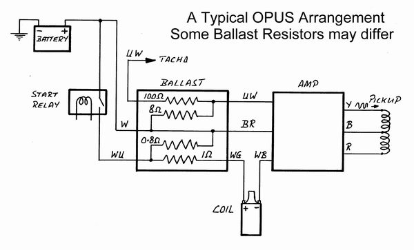
This is the wiring for the original Opus Ignition System, the Start relay is where I connected the remote button to crank the engine, The Ballast is the Resistor unit was on the bench along with the Ignition coil. The Pickup is the small Hall Effect sensor in the Distributor with the three wires. The disc/second rotor with the small metal rods that the sensor reacts to is not shown. The coil was also on the bench.
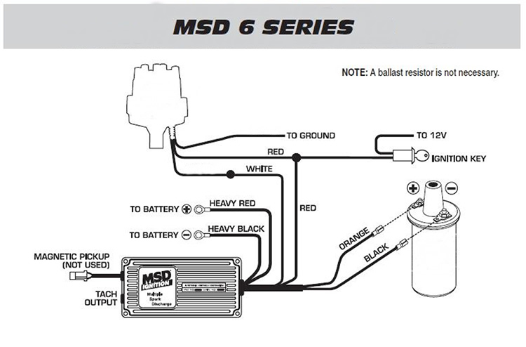
Below is the replacement system I fitted, with the MSD Digital 6A Ignition Controller 6201 the Coil was a MSD Blaster HVC Ignition Coil 8252 the wires going to the Distributor to the replacement LED unit I have in there, which seems to be unavailable now. As it has been a few years since I replaced this unit. It was an Crane Optical trigger but it had a Square wave output required by the Controller MSD 6A. I think now a pickup sensor could be fitted to Distributor using the original Disc/second rotor to trigger it. If the magentic field from the original Disc/second rotor is strong enough. I fused the MSD 6A unit with a ten amp fuse, The LED sensor I fitted ran with 12v power, from the ignition switch but it may be the case with a later sensor used in its place may only be a 5v feed so make sure what is required. The NOTE is refering to a ballast resistor for the Ignition coil. Note :- Looking at the spec sheets for the MSD Digital 6A it only shows fittment for up to a 8 cylinder. So I checked the number of impulses a sec it could cycle. Then looking at the max revs of the V-12 and firing strokes a minute, the Digital 6A was well inside its limit.
|